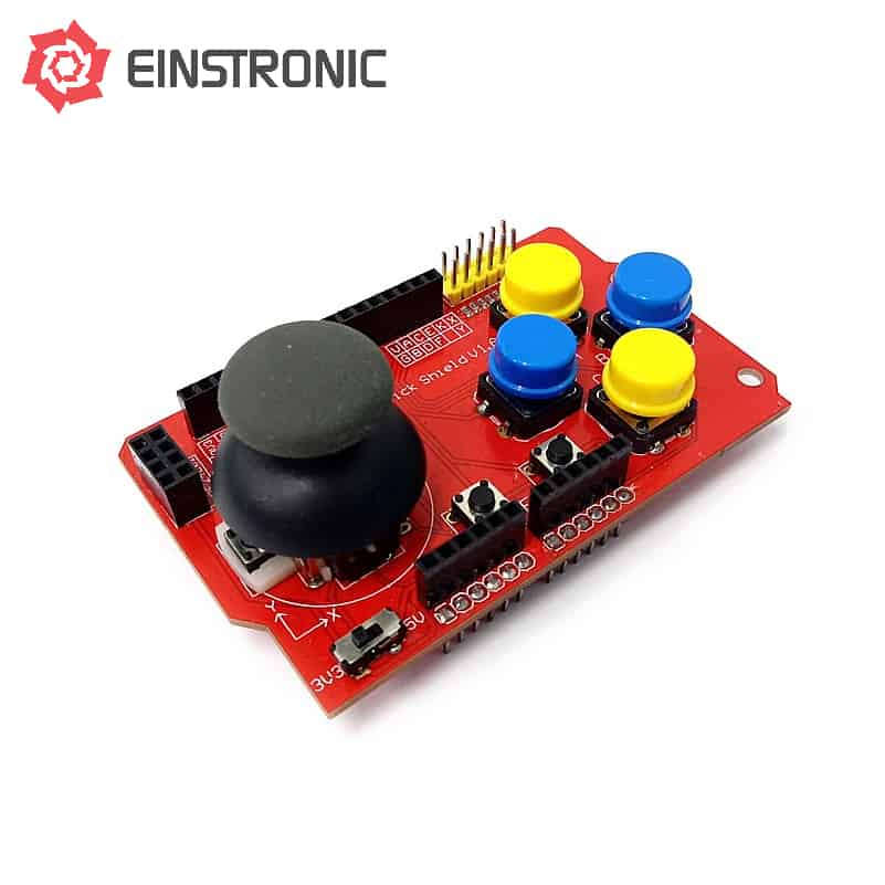
DescriptionThe joystick Shield V1.A will let you turn your Arduino board into a controller like the game console system. It can be used to control anything from a remote control car to anything that you can think of. It also provides a lot of different interfaces.Please read the tutorial below how to use this joystick shieldJOYSTICK SHIELD V1.A – THE ARDUINO STOREFunduino (Arduino Joystick Shield) Controlled Robot – MakerPro FeaturesTwo-axis thumb joystick like the one from playstation that connects to two analog pinsnRF2401 RF interfaceNokia 5110 LCD interfacebluetooth interfaceI2C interfaceRS232 interfacePush buttons use 2, 3, 4, 5, 6,and 7 digital pinAnalog joystick use 0, and 1 analog pin PowerThe shield has a slide switch that allows you to select whether you are using it with a 5V board like an Arduino Uno or a 3.3V MCU like the Arduino Due. Be sure to set it to the correct voltage for the board you are using. 2-Axis JoystickThe X-Axis potentiometer of the joystick is connected to A0. The Y-Axis potentiometer is connected to A1. The analog inputs on a microcontroller read values over a range of 0-1023 (for typical 10-bit ADC inputs). The X-Axis and Y-Axis controls should read around 512 (midpoint) when the control is at rest. As the joystick is moved, one or both of the controls will register higher or lower values depending on how the control is being moved. The joystick also has a button ?K? which is activated by pressing the joystick down. This button is connected to D8. Push ButtonsThere are a total of 6 buttons on the board (not including the one on the joystick) labeled A-F. The 4 large buttons are typically used for up/down/left/right or similar functions. The two smaller buttons are typically used for less commonly used functions such as ?select? or ?start? since they are less accessible / less likely to be pressed accidentally. All buttons have pull-up resistors and pull to ground when pressed.Button A ? Connects to D2Button B ? Connects to D3Button C ? Connects to D4Button D ? Connects to D5Button E ? Connects to D6Button F ? Connects to D7 Bluetooth slotThe RX/TX lines are brought out to a separate 4-pin female header along with 3.3V and Ground. This can be used for connecting a 4-pin 3.3V Bluetooth device or a TTL serial device. I2C interface slotThe I2C SDA and SCL lines are brought out to a separate 4-pin male header along with 5V and Ground. This is in addition to the normal A4/A5 location of these lines. This allows for easy attachment of I2C devices. nRF24L01 slotThis connector allows an nRF24L01 RF transceiver module to be plugged in 2 x 4 Female HeaderGND ? Ground.VCC ? 3.3VCE ? Connects to D9CSN ? Connects to D10SCK ? Connects to D13MOSI ? Connects to D11MISO ? Connects to D12IRQ ? No Connection Nokia 5110 LCD slotThis female header connector is designed to mount the Nokia 5110 LCD that was originally designed for Nokia phones and provides a 48?84 pixel matrix. This interface occupies the same D9-D13 pins as the nRF24L01, so you can?t use both at the same time. Interface ConnectorThis dual row yellow male header connector provides another point of access to all the buttons, joystick pots, 3.3V, 5V and Ground. The pin-out of this connector is labeled on the board to the left of the connector.